Обзор продукта
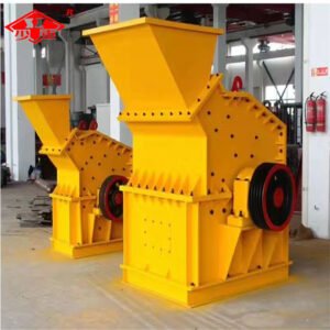
Гидравлическая двухвалковая пескоструйная машина, также известная как гидравлическая двухвалковая дробилка или гидравлическая двухвалковая пескоструйная машина, является модернизированной версией пружинной двухвалковой пескоструйной машины. В ней традиционный пружинный механизм заменен гидравлической системой. Подходит для среднего и мелкого дробления твердых материалов с прочностью на сжатие ниже 250 МПа и влажностью ниже 351 Тп3Т, таких как речная галька, железная руда, кварцит и известняк. Широко применяется в горнодобывающей промышленности, тепловой энергетике, цементной и керамической промышленности, металлургии, химической промышленности и производстве строительных материалов.
Принцип работы
Гидравлическая двухвалковая машина для производства песка оснащена двумя высокопрочными валками, вращающимися в противоположных направлениях. Когда материал попадает в узкий зазор между валками, он подвергается интенсивному сжатию, сдвигу и измельчению, что приводит к дроблению на более мелкие частицы. Интеллектуальная гидравлическая система автоматически регулирует зазор между валками в зависимости от твердости материала, обеспечивая стабильную производительность дробления и размер частиц на выходе.
Основные компоненты гидравлических двухвалковых пескоструйных машин
1. Гидравлический роликовый узел
Эта конструкция состоит из пары износостойких роликовых оболочек и роликовых валов, где оболочки образуют непосредственную поверхность дробления, а валы передают крутящий момент. Данный узел является основным рабочим компонентом для прессования материала и производства песка.
2. Интеллектуальная гидравлическая система
Включает в себя гидравлический насос, гидравлический цилиндр, предохранительный клапан, аккумулятор и т. д. Точно регулирует зазор между валками, обеспечивает давление сжатия и защиту от перегрузки посредством автоматического откатывания;
3. Приводной узел
Включает в себя двигатель, редуктор, муфту/редуктор. Обеспечивает стабильную, согласованную скорость вращения и крутящий момент на валах валов, гарантируя синхронное противовращение обоих валов;
4. Механизм регулировки зазора между осями подвески и кузовом
Взаимодействуя с гидравлической системой, это обеспечивает основной контроль размера частиц на выходе, позволяя точно и плавно регулировать его в диапазоне 1-3 мм;
5. Рама и корпус подшипника
Благодаря использованию прочной сварной/литой стальной рамы в сочетании с высокопрочными самоустанавливающимися подшипниковыми узлами, она выдерживает сдавливающие и деформирующие нагрузки, обеспечивая при этом структурную жесткость и эксплуатационную стабильность всей машины.