")
Обзор продукта
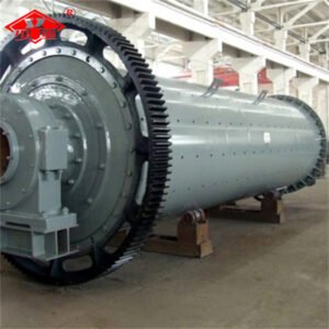
Спиральный классификатор, производимый нашей компанией, — это традиционное и эффективное оборудование, использующее принцип различной скорости осаждения твердых частиц в жидкости для классификации. Он состоит в основном из U-образного переливного устройства, спирального механизма, передающего устройства и подъемного механизма. Благодаря своей прочной конструкции, плавной работе и высокой эффективности сортировки, он является надежным выбором для измельчения и сортировки в современных обогатительных фабриках. В зависимости от высоты переливного порога его можно разделить на два основных типа: тип с высоким переливным порогом (подходит для отделения крупных частиц > 0,15 мм) и тип с низким переливным порогом (подходит для отделения мелких частиц < 0,15 мм).
Сценарии применения:
Предварительная сортировка: Перед поступлением материала в мельницу проводится сортировка мелкозернистого сырья, соответствующего установленным требованиям, для повышения эффективности работы мельницы.
Контроль качества и сортировка: Создание замкнутого контура с шаровой мельницей для контроля тонкости помола конечного продукта (основное применение).
Очистка от ила и обезвоживание: используется для концентрированного обезвоживания при промывке, удалении ила или образовании пульпы.
Принцип работы
Принцип работы спирального классификатора основан на гравитационном осаждении и механическом переносе.
1. Смешивание и отстаивание:
Шлам, выгружаемый шаровой мельницей, поступает в нижнюю часть U-образного резервуара через боковой загрузочный патрубок классификатора. В относительно спокойных водоемах крупные и тяжелые частицы быстро оседают и быстро опускаются на дно желоба. Мелкие и легкие частицы оседают медленно и остаются во взвешенном состоянии в верхнем слое шлама.
2. Разделение и перелив:
Уровень суспензии, содержащей мелкие частицы в верхнем слое, продолжает подниматься, переливаясь через переливной порог и превращаясь в продукт перелива (качественные мелкие частицы), который направляется на следующий этап сортировки.
3. Транспортировка и возврат песка:
Установленное в нижней части резервуара спиральное устройство непрерывно вращается, выталкивая и извлекая крупные частицы (возвратный песок), осевшие на дне резервуара, по диагонали, и, наконец, выгружая их через верхнее выпускное отверстие для повторного измельчения в шаровую мельницу.
4. Регулировка подъема:
Высоту спиральных лопастей можно регулировать с помощью подъемного устройства, что позволяет изменять площадь осаждения, точно настраивать размер частиц и производительность обработки.
-
Основные компоненты спирального классификатора
1. Корпус танка
Наклонная канавка, обычно U-образной или полукруглой формы, служит пространством для удержания пульпы и завершения выравнивания грунта при осадке.
2. Спиральное устройство
Основные компоненты, включая шпиндель, спиральные лопасти, кронштейны и чугунные футеровки. Он отвечает за перемешивание суспензии для предотвращения осаждения и выталкивание осадка вверх.
3. Передающее устройство
В комплект входят двигатель, редуктор и зубчатая передача для привода спирали и регулировки скорости.
4. Подъемное устройство
Он используется для подъема шнека во время остановки, чтобы предотвратить его засыпание песком и облегчить следующий запуск. В крупных классификаторах обычно используются электрические или гидравлические подъемные механизмы.
5. Подшипники и подшипники
Верхний и нижний подшипники используются для поддержки спирального шпинделя и обеспечения его плавной работы.
")


")
")
")