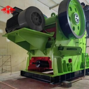
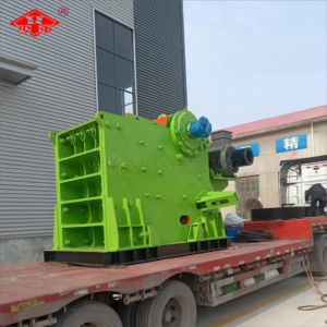
Product Overview
Double-roll crusher, a type of mining machinery also known as a twin-roll crusher. Primarily used for crushing ore. This machine boasts compact dimensions, a high crushing ratio (5-8), low noise levels, simple construction, and straightforward maintenance. It delivers uniform particle size of crushed material, low over-crushing rates, convenient servicing, sensitive overload protection, and reliable safety. Suitable for coal, metallurgy, mining, chemical, and building materials industries, it is particularly well-suited for crushing raw coal (including gangue) in large coal mines or coal preparation plants. The tooth roller crusher boasts substantial crushing capacity. A limit-type hydraulic coupling connects the motor to the reducer, preventing power overload. Sensor overload protection ensures safety and reliability. Roller spacing is hydraulically adjustable, with centralised lubrication for roller bearings. Optimised tooth design employs shear force for selective crushing, delivering high efficiency, low consumption, and uniform particle size.
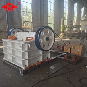
Working Principle
The spring-loaded double-roll crusher features two parallel rollers driven by independent motors to rotate in opposite directions. When material enters the gap between the rollers, it undergoes a combined action of compression, shearing and splitting to achieve crushing. The spring mechanism automatically adjusts the roller gap by compressing or releasing according to changes in material hardness or particle size, ensuring crushing force remains within an optimal range at all times.
The core component of the spring-loaded double-roll crusher
1. Crushing Rollers
These components directly perform the crushing task, comprising hollow shafts forged or cast from high-strength alloy steel, along with wear-resistant roller sleeves. The sleeves are replaceable, with material selection based on the abrasiveness of the processed material, such as high-manganese steel or high-chromium cast iron.
2. Spring Assembly
Balances the compressive force between crushing rolls, providing overload protection. During overload conditions, springs compress, allowing the movable bearing to shift and widen the discharge opening for expelling uncrushed material. The assembly subsequently returns to its original position under spring tension.
3. Transmission System
Typically comprising a motor, drive and driven pulleys, and V-belts, this system transmits power from the motor to the crushing rollers, causing them to rotate in opposite directions to perform the crushing function.
4. Adjustment Mechanism
Used to regulate the gap between the two crushing rollers, thereby controlling the output particle size. This is achieved by adding or removing shims between the roller bearings, or by adjusting the nuts on the spring covers.