Product Overview
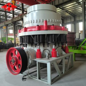
The hydraulic cone crusher is a modern medium-fine crushing device integrating mechanical, hydraulic, electrical and intelligent control systems. This equipment employs a hydraulic system in place of traditional spring mechanisms, achieving fully automated control over discharge opening adjustment, oversize protection, and cavity cleaning operations. Its unique laminar crushing principle utilises multi-point hydraulic control to precisely synchronise the swinging frequency and stroke of the moving cone. This subjects materials to multiple compressions and impacts within the crushing chamber, enabling effective processing of medium-to-high hardness materials while delivering uniform particle shape and high cubic content. The intelligent control system continuously monitors operational parameters, automatically optimising chamber configuration and working conditions to maintain crushing efficiency while significantly reducing energy consumption. With its intelligent operation, high productivity, low energy consumption, and stable reliability, the hydraulic cone crusher has become the core crushing equipment for large and medium-sized mining operations and aggregate projects.
Working Principle
During operation of the HP hydraulic cone crusher, the motor drives the eccentric sleeve to rotate via a V-belt, drive shaft, and bevel gear pair. Under the action of the eccentric sleeve, the movable cone performs a swinging motion, causing the movable and fixed cones to alternately approach and separate. Material within the crushing chamber is continuously crushed through compression and impact, with the crushed material discharged from the lower section.
HP Multi-Cylinder Hydraulic Cone Crusher Core Components
1. Main Frame and Transmission System
A high-strength monobloc cast frame provides core support. The motor drives the horizontal shaft and a pair of spiral bevel gears via pulleys, causing the eccentric sleeve to rotate around the fixed main shaft.
2. Crushing Core Assembly
Comprising the moving cone assembly (fitted with the upper crushing wall) and fixed cone assembly (fitted with the upper bowl liner). The moving cone performs a swinging motion driven by the eccentric sleeve, achieving continuous compression crushing of materials.
3. Hydraulic System
Comprising multiple locking/release hydraulic cylinders, a hydraulic power unit, and piping. This system manages functions including oversize material protection, discharge opening adjustment, and frame locking, forming the core of the equipment’s automated control.
4. Adjustment and Lubrication System
The adjustment ring alters the fixed cone position to regulate discharge opening size. An independent lubrication system employs thin oil to lubricate and cool all bearings and friction pairs.