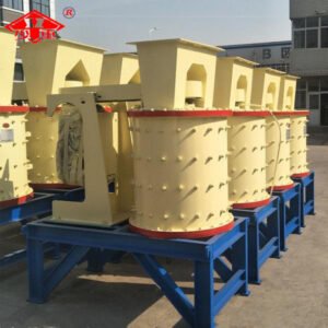
Rod Mill Sand Maker

Feed Size:
≤ 25 mm
Capacity:
0.65-200T/H
Applicable Materials:
Feldspar, quartz, ores, refractory materials, cement, steel grit, slag powder, copper ore, iron ore, gold placers, concrete aggregates, asphalt aggregates, etc.
Application Range:
Widely employed in metal and non-metal mines, as well as in the water conservancy and building materials sectors, for grinding various ores or rocks.

This equipment controls the output particle size (e.g., 0.075–0.89 mm) by adjusting parameters such as the number of grinding rods, feed particle size, and water flow velocity. It employs an open-circuit wet production process to prevent over-grinding of rare metals.

Description

Product Overview

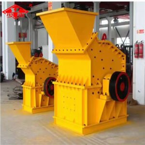
The rod mill sand-making machine is a highly efficient sand-producing apparatus utilising steel rods as grinding media. Primarily employed for crushing hard and brittle materials such as feldspar, quartz, and ores, it is suitable for aggregate processing and fine mineral crushing within sectors including building materials, metallurgy, and mining. Its core structure comprises a rotating cylinder, a reduction transmission system, and steel rod media. Material pulverisation is achieved through centrifugal and frictional forces, with compatibility for low-speed synchronous motors or gear reducers as drive units.


Working Principle

The rod mill sand-making machine is driven by an electric motor via a reduction gearbox and peripheral large gear, or directly by a low-speed synchronous motor through the peripheral large gear, causing the cylinder to rotate. The cylinder contains suitable grinding media—steel rods. Under the combined effects of centrifugal force and friction, the grinding media are elevated to a certain height before being discharged in a projectile or free-fall state. The material to be ground is continuously fed into the cylinder through the feed inlet, where it is crushed by the moving grinding media. The product is then discharged from the machine via the combined forces of overflow and continuous feeding, ready for subsequent processing stages.

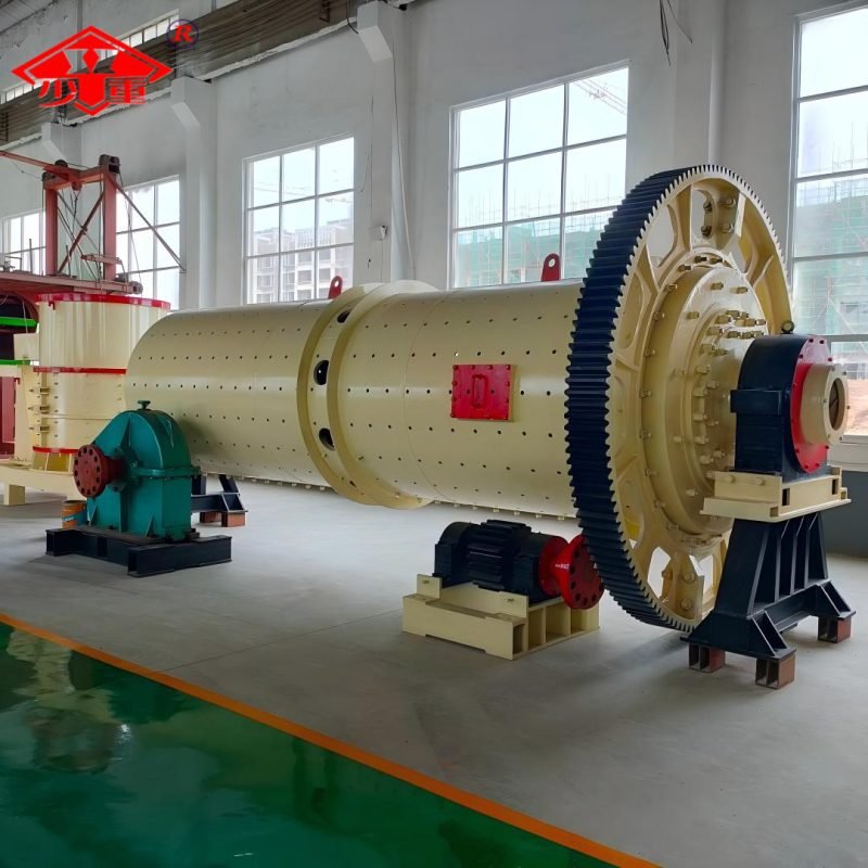
Core Components of a Ball Mill

1. Cylinder:
As the core grinding chamber, it houses steel rod media within which materials are pulverised through the impact and discharge action of the falling rods.

2.Drive System:
Comprising a reduction gearbox, large and small gears, or a low-speed synchronous motor, this system transmits power from the motor to the cylinder, driving its rotation.

3.Steel Rod Media:
Serving as the direct grinding medium, these rods impact and grind materials through movement within the cylinder. Their length, diameter, and filling volume directly influence output particle size and efficiency.

4. Feeding and Discharging Devices:
The feeding device continuously conveys material into the cylinder, while the discharging device expels the crushed product via overflow or continuous discharge force.

5. Lubrication system:
Lubricates critical components such as main bearings and gears to reduce wear, lower failure rates, and extend equipment lifespan.

6.Slow-speed drive unit:
Used after prolonged equipment shutdown to rotate the drum and break up any material that may have caked inside, ensuring smooth restarting.

Features

  • Energy savings

Achieves over 40% energy savings compared to older equipment. Produces more uniform particle sizes with fewer coarse particles and less fines.

  • Product particle size is uniform

When coarse particles are entrained within the material ascending along the liner, the rod mill allows fine particles to pass through the gaps, which also facilitates the crushing of coarse particles.

  • High throughput

During the grinding process, the grinding media in rod mills make line contact with the ore, thereby exhibiting a degree of selective grinding action.

  • Less over-grinding occurs

The particle size characteristics of rod mill products are related to the grinding process of ore within the mill. When the rods strike the ore, they first impact the coarse particles before grinding the finer ones, thereby reducing the risk of over-grinding.


Technical Parameters

Specification model Barrel Size (mm) Effective volume of cylinder (m3) Ball loading capacity (t) Cylinder speed (r/min) Power (kw) Discharge particle size (mm) Output (t/h) Weight
(t)
Diameter × length
MB0918 φ900×1800 2.3 29 22 2.5-0.2 6-1.6 6.2
MB0924 Φ900×2400 3.1 29 30 2.5-0.2 10-2.9 6.6
MB1224 Φ1200×2400 6.5 27 55 2.5-0.2 13-5 13.5
MB1530 Φ1500×3000 5.0 8 23 75 2.5-0.2 12-5.5 16.71
MB1830 Φ1800×3000 6.5 17 22.8 132 2.5-0.2 20-9.5 29.8
MB2122 Φ2100×2200 6.7 18 20.9 160 2.5-0.2 27-12 42.5
MB2130 Φ2100×3000 9.2 25 20.9 160 2.5-0.2 30-13 43.9
MB2136 Φ2100×3600 11.0 28 20.9 200 2.5-0.2 35-14.8 49.4
MBZ2136 Φ2100×3600 11.0 32.5 20.9 210 -5.0 61.5-43 49.9
MB2140 Φ2100×4000 12.2 31 20.9 220 2.5-0.2 38-17 50.3
MB2145 Φ2100×4500 13.8 35 20.9 250 2.5-0.2 43-19 51.8
MB2430 Φ2400×3000 12.2 31 19 250 2.5-0.2 47-22 56.0
MBZ2430 Φ2400×3000 12.2 31 19 250 -5.0 73-52 58.3
MB2436 Φ2400×3600 14.6 37 19 280 2.5-0.2 55-26 61.0
MBZ2436 Φ2400×3600 14.6 37 19 280 -5.0 84-60 62.4
MB2730 Φ2700×3000 15.3 35 17.5 315 5-0.8 125-37.5 75.6
MB2736 Φ2700×3600 18.4 42 17.5 355 5-0.8 150-45 81.8
MB2740 Φ2700×4000 20.5 47 17.5 400 5-0.8 165-50 84.3
MB3040 Φ3000×4000 25.9 50 16.2 500 5-0.8 206-62 130
MB3245 Φ3200×4500 33 56 15.5 630 5-0.8 228-70 138
MB3248 φ3200×4800 34 60 15.5 710 5-0.8 240-74 142
MB3645 Φ3600×4500 40.8 78 14.5 800 5-0.8 270-83 168
MB3654 Φ3600×5400 50 94 14.5 1000 5-0.8 340-103 192